Installation method of AL-310sY on Y-axis
Installation method of AL-310sy on milling machine's Y-axis,Because AL-410sY AL-510sY and AL-310sY have the same overall dimensions, and installation dimensions, their installation methods are also referred to in this paper.
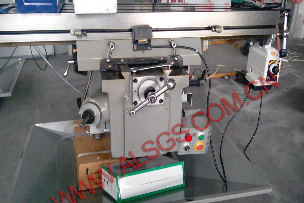
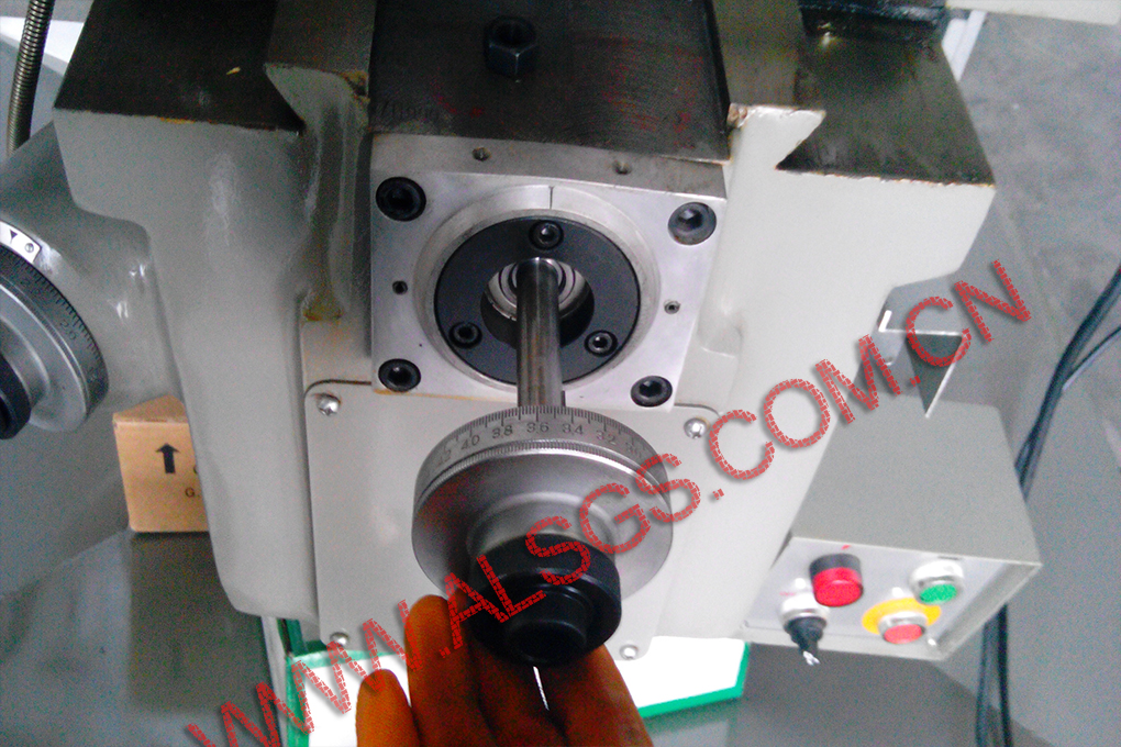
1、Effect of milling machine Y-axis without ALSGS electronic power feed.(Refer to the figure below)
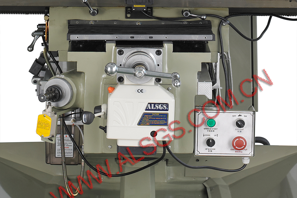
2、When the ALSGS power feed of milling machine is installed, the effect of Y-axis is shown in the figure.
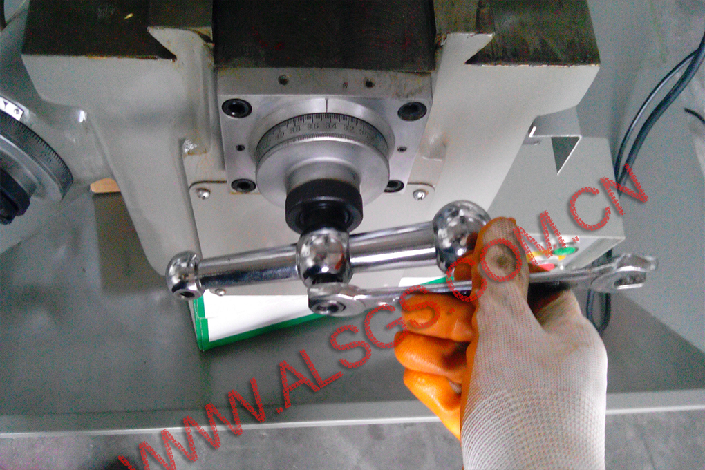
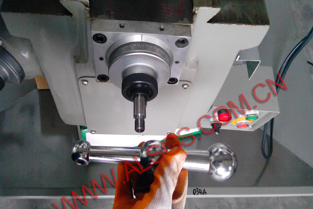
3、Remove the locking nut, handle and dial on the Y-axis screw rod of the milling machine in turn.
(1)First, fix the handle and use the wrench to rotate the lock nut counterclockwise to exit the nut.
(2)Pull the handle backward to release it from the screw rod.
(3)At this time, the key inside the handle is exposed, and the tool is used to take out the key.
(4)Pull the dial backward, and the dial and flange can be separated from the screw rod.
(5)The removed accessories should be kept properly, which will be used in the later reset installation.
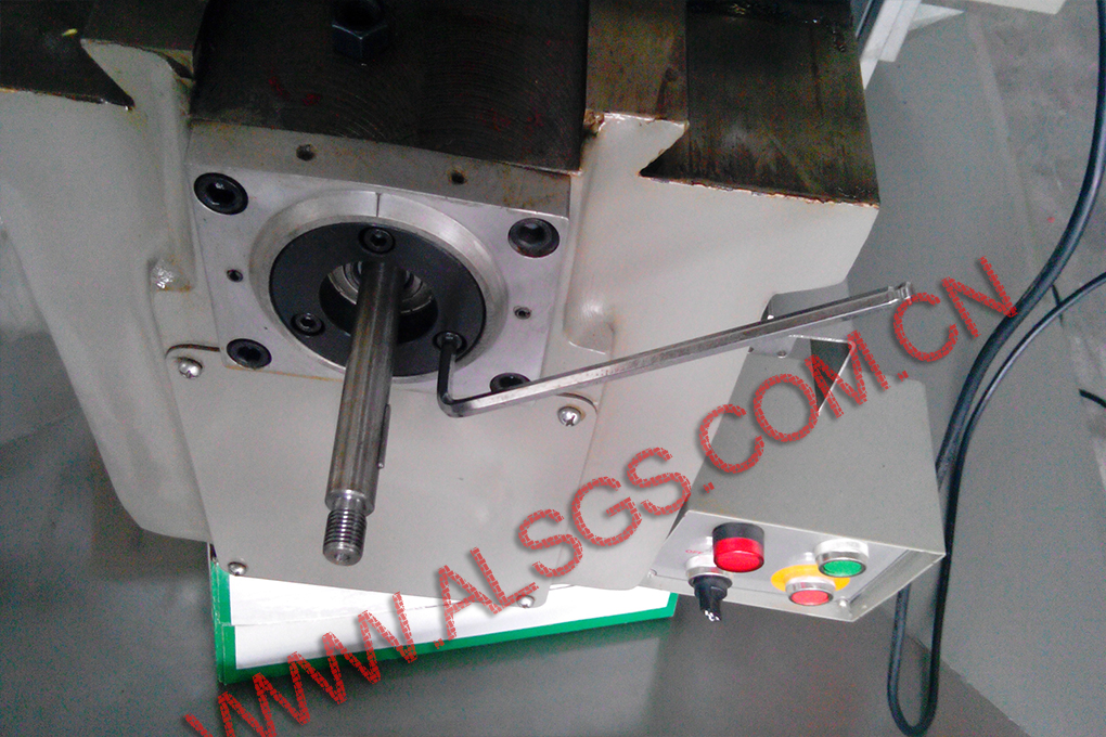
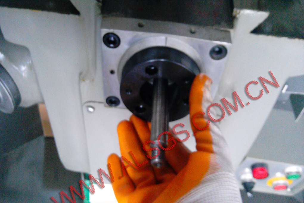
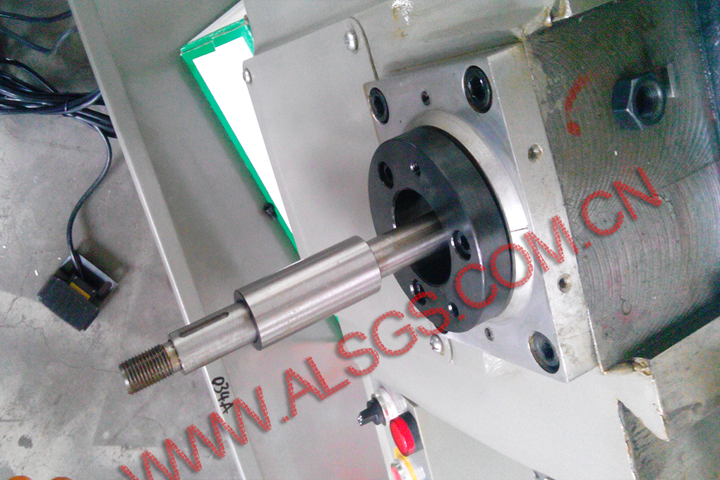
4,Remove the bearing flange of y-axis screw seat of milling machine.
(1) Remove the three fixing screws of the bearing flange of the Y-axis screw seat of the milling machine.
(2) Take out the bearing flange of y-axis screw seat of milling machine.
(3) At this time, the screw rod is lack of support, and has been separated from the machine tool, only relying on the screw nut and bearing connection.
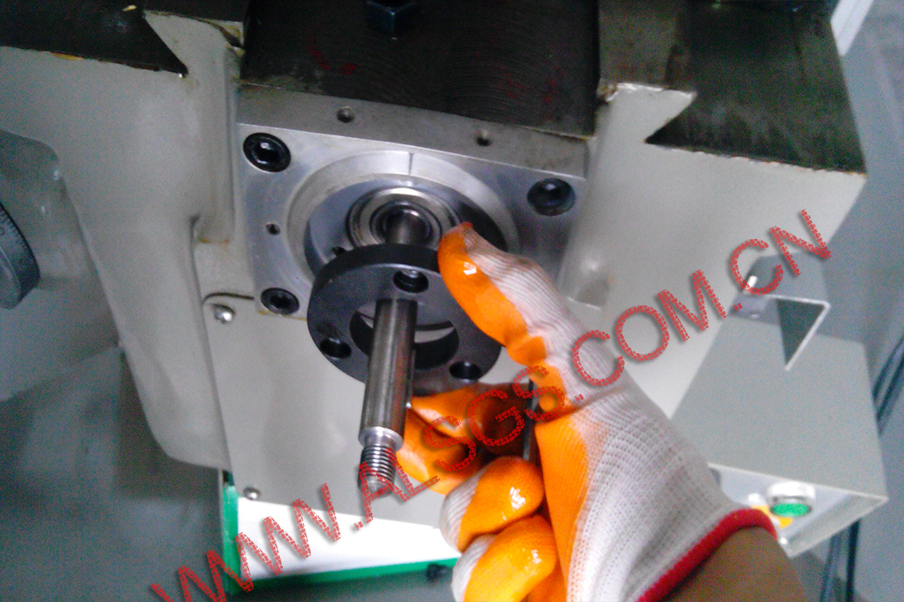
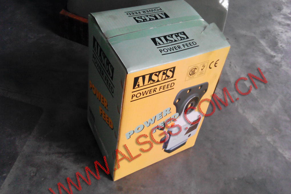
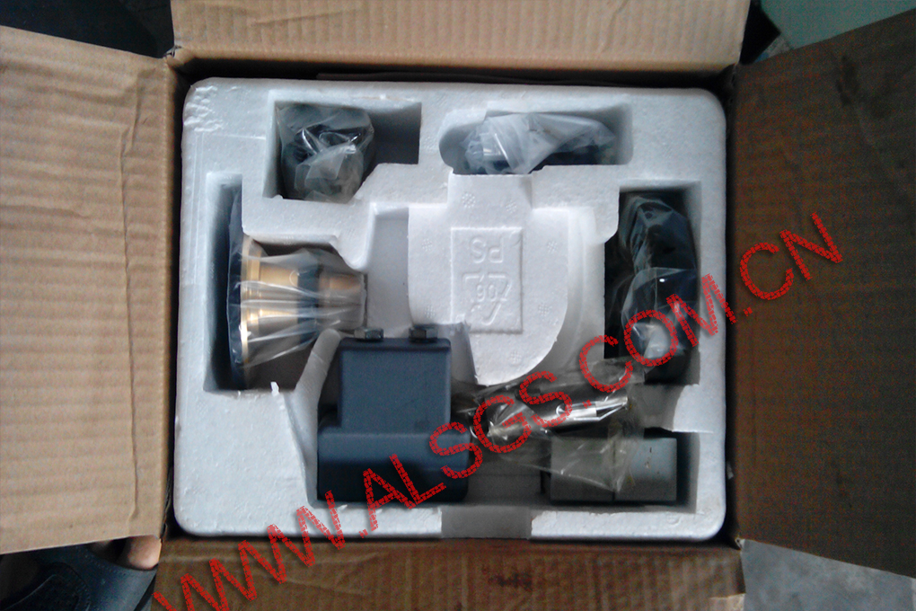
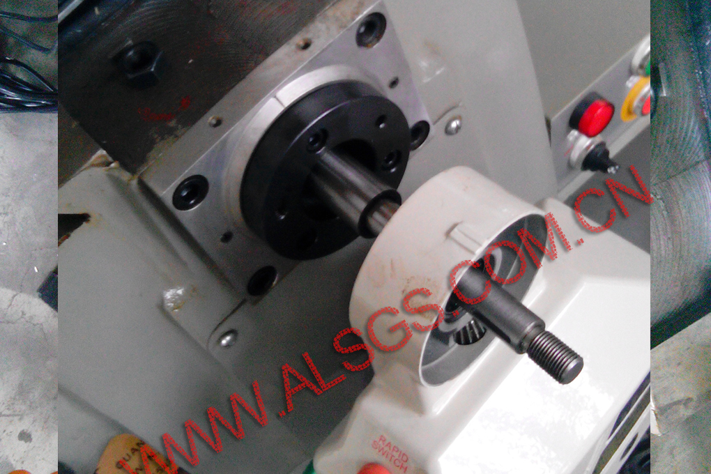
5、Take out AL-310sY, open the packing box and take out the fixed flange. Install the flange at the position of the original screw seat bearing flange.

6、Install the connecting plate of the x-axis cutter feeder of the milling machine.
(1) Install the thickened flange to replace the original screw seat bearing flange.
(2) Install the screw removed from the screw holder in the screw hole of the connecting plate and lock it.
(3) As the y-axis does not remove the screw seat, it is not necessary to align the center hole.
(4) The thickened flange has two screw holes, which are used to fix the cutter body, with the screw holes facing outward.
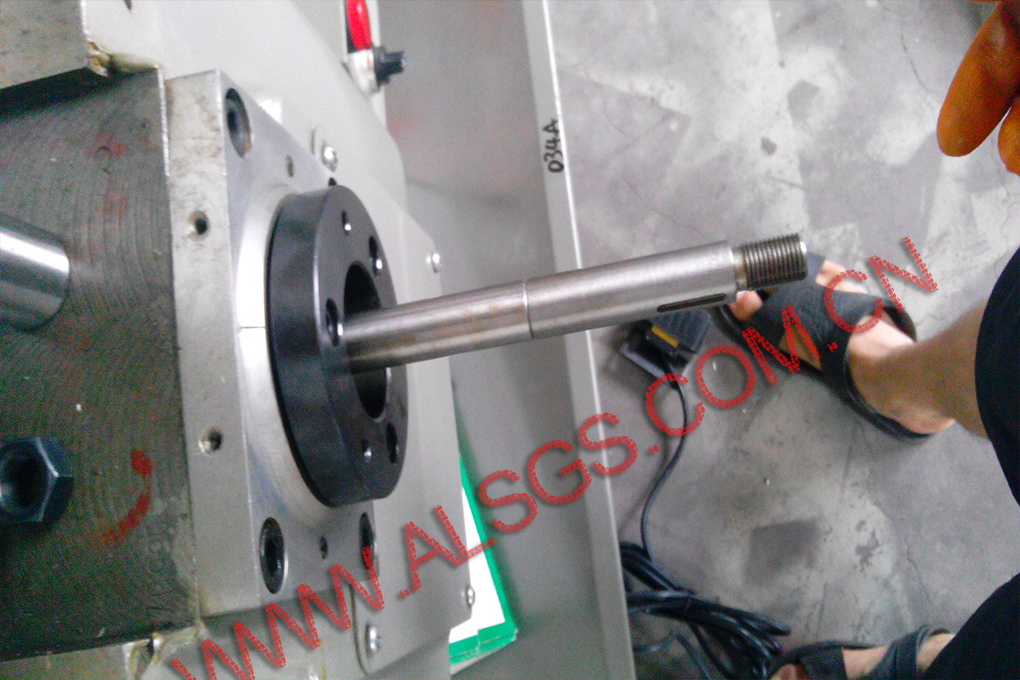
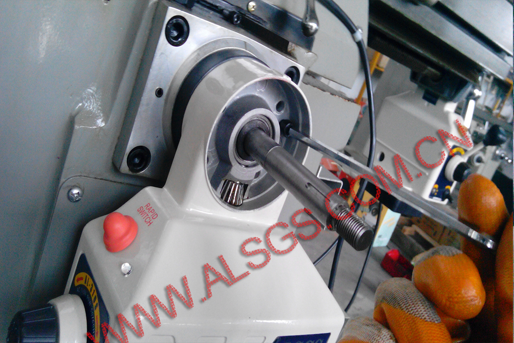
7、Install the screw extension kit.
(1) Because the length of y-axis lead screw is not enough and there is no installation position, it is necessary to use the lead screw extension kit.
(2) The extension sleeve is installed at the end of the y-axis screw rod. The screw rod should be fixed and rotated clockwise to lock the extension sleeve.
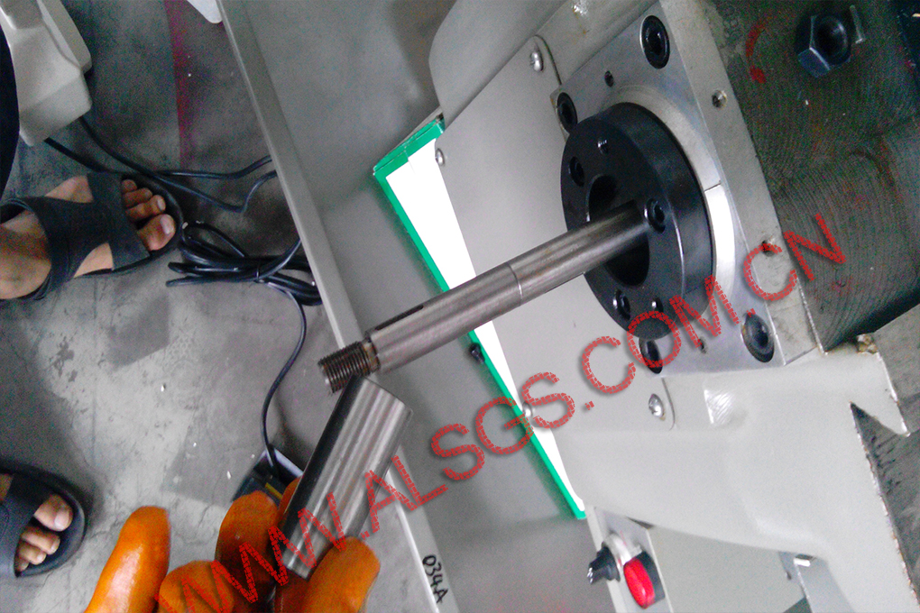
8、Install the screw reducer sleeve.
(1) Install the reducing sleeve on the screw rod.
(2) Push to the bottom.
9、Install the cutter feeder body.
(1) Take out the cutter feeder.
(2) Push in the reducing sleeve, push it to the bottom and tighten the fixing screw.
Install the cutter feeder body.
(1) Take out the cutter feeder.
(2) Push in the reducing sleeve, push it to the bottom and tighten the fixing screw.
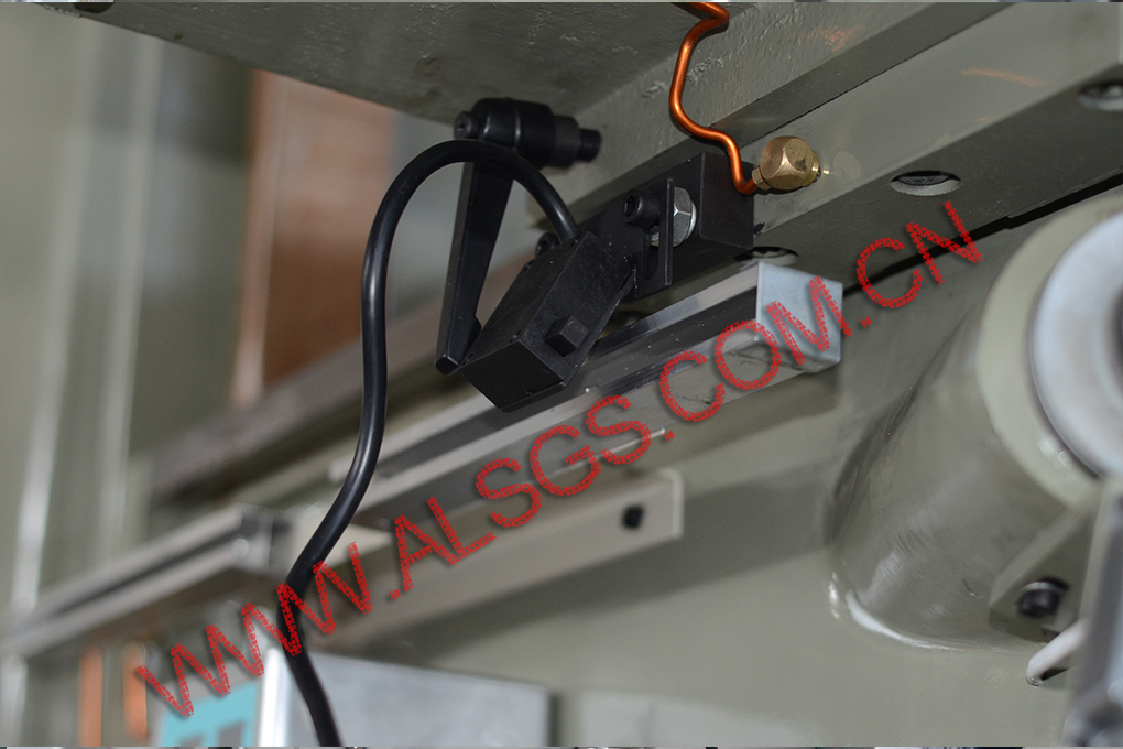
11、Install the limit stop
(1) The position of the limit block is different according to different machine tools.
(2) The installation principle of the limit block is to make the limit switch move with the worktable, and the position of the limit block is fixed. When the machine tool reaches the limit travel position, the trigger switch will stop the feeder.
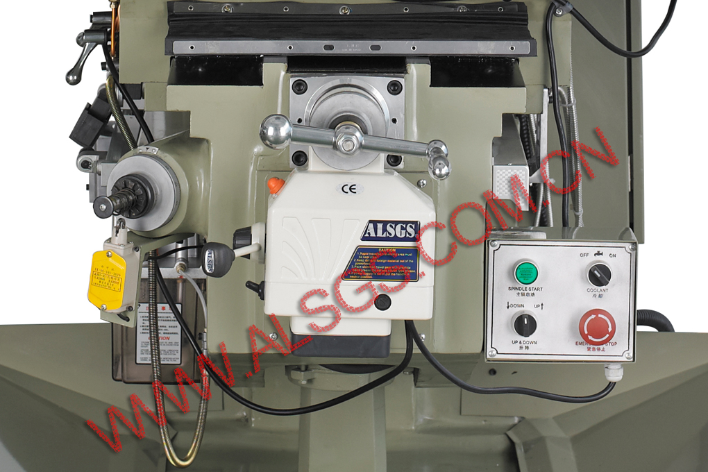
 12、The installation is complete.
The effect after installation is shown in the figure.
ALSGS Product catalog
ALSGS Electronic power feed:
AL-310S AL-310SX AL-310SY AL-310SZ
AL-410S AL-410SX AL-410SY AL-410SZ
AL-510S AL-510SX AL-510SY AL-510SZ
ALB-310S
ALSGS Mechanical power feed:
AL-206X AL-206Y AL-206XB
ALSGS Clamping kit : 58 piece suit 42 piece suit 36 piece suit
ALSGS Precision vises: 8inch 10inch 12inch 18inch
ALSGS accessories: Nylon gear Potentiometer Micro switch

 ALSGS NEWS
